
U-Shaped Kitchen Layouts: The B2B Engineering Guide
As an architectural millwork and custom cabinetry manufacturer, ALLAND collaborates with residential developers, commercial general contractors, and interior architects to engineer high-performance u shaped kitchen layouts for single-family estates and multi-family projects. The kitchen spatial layout functions as the operational core of residential space management, directly impacting property valuation, spatial ergonomics, and long-term mechanical durability. Among all perimeter configurations, a custom u shaped layout kitchen provides an uninterrupted envelope that eliminates cross-traffic interference, maximizes counter surface square footage, and optimizes storage volume.
However, transforming an architectural blueprint into a code-compliant U-shaped kitchen requires far more than arranging off-the-shelf modular boxes. It demands an intimate technical understanding of North American building codes, National Kitchen & Bath Association (NKBA) clearance standards, architectural millwork tolerance engineering, and complex hardware integration. From mitigating mechanical friction across blind corners to accommodating non-plumb framing drywall (>90°) with calibrated scribing, execution requires absolute precision. This technical manual provides trade professionals with the exact dimensional metrics, structural specifications, and factory-direct millwork strategies required to engineer and install world-class U-shaped culinary spaces.
U Shaped Kitchen Layout Dimensions: NKBA Clearance Standards & Structural Clearances
The difference between an institutional luxury kitchen and a compromised residential installation lies in dimensional rigor. When specifying u shaped kitchen layout dimensions, millwork engineers must strictly adhere to NKBA planning guidelines while accounting for real-world framing tolerances, appliance door swings, material deflection, and municipal building inspection standards. Failing to calculate net clear passageways during the rough-in framing phase leads to expensive field modifications and delayed certificate of occupancy permits.
| Metric Parameter | Single-Cook Standard | Multi-Cook / Commercial Grade | ADA Accessibility Compliant |
| Net Aisle Clearance | 42 Inches (1067 mm) Min. | 48 Inches (1219 mm) Recommended | 60 Inches (1524 mm) Turning Diameter |
| Minimum Bottom Wall Width | 108 Inches (2743 mm) Min. | 120 Inches (3048 mm) Preferred | 132 Inches (3353 mm) Preferred |
| Triangle Leg Distance | 4 Feet (1219 mm) Min. | 9 Feet (2743 mm) Max. | 4 Feet (1219 mm) Min. |
| Total Triangle Perimeter | 12 Feet (3658 mm) Min. | 26 Feet (7925 mm) Max. | 26 Feet (7925 mm) Max. |
| Countertop Vertical Height | 36 Inches (914 mm) Standard | 36 Inches (914 mm) Standard | 34 Inches (864 mm) Max. Height |
Architectural dimensioning in U-shaped footprints must account for structural wall plumbness. Residential framing in North America routinely exhibits variances of up to 1/2″ over an 8-foot vertical run, alongside non-square 90° corner framing. Millwork engineering addresses these physical realities by specifying a 3/4″ scribe allowance on blind corner panels and end fillers. This ensures that when custom cabinets are leveled and scribed to fit imperfect drywall, the internal net clearances between opposing cabinet faces maintain the strict 42″ or 48″ NKBA thresholds without compromising drawer box extraction or mechanical hardware operation.
Standard U-Shaped Kitchen Layout Dimensions & Modular Clearances
Executing a functional U-shaped kitchen requires strict adherence to modular floor plan engineering. The absolute minimum overall room width for an enclosed U-shaped layout is 8 feet (96 inches / 2,438 mm). This footprint accommodates two standard 24″ (610 mm) deep perimeter base cabinet runs flanking a central 48″ (1,219 mm) open work corridor.
When establishing kitchen cabinet width dimensions, casework increments strictly follow standard 3″ (76 mm) modular steps (9″ to 36″). Standard wall cabinets feature nominal depths of 12″ to 14″ (305 to 356 mm) and are hung precisely 18″ (457 mm) above the finished countertop, ensuring ample clearance for countertop small appliances and under-cabinet LED light extrusions.
NKBA Aisle Width Guidelines: 42-Inch vs. 48-Inch Work Aisles
According to NKBA guidelines, net aisle clearances must be measured strictly between the outermost finished surfaces (including countertop overhangs and handle profiles), rather than raw cabinet boxes:
42″ (1,067 mm) Single-Cook Clearance: Establishes the baseline for single-occupant food preparation.
48″ (1,219 mm) Multi-Cook Standard: Essential in luxury residences to allow an open dishwasher door or dropped range oven door to coexist with an opposing pullout drawer without blocking traffic.
⚠️ Why this matters for your jobsite: In real-world installations, uncalculated 1-1/2″ stone overhangs and protruding bar handles can narrow a 42″ rough aisle below legal inspection thresholds. ALLAND’s CAD engineering desk digitally simulates every appliance door-swing radius against opposing drawer banks before manufacturing begins.
Kitchen Cabinet Width Dimensions & Net Clearance Mechanics
To maintain architectural equilibrium and visual symmetry, the bottom wall of a U-shaped run—which typically houses the primary cooking range or workstation sink—demands strict minimum dimensioning rules. The absolute minimum recommended bottom wall framing length is 108″ (2,743 mm). This specific threshold accommodates two standard 24″ (610 mm) deep base cabinet runs on the opposing parallel legs, plus two 36″ (914 mm) corner cabinet footprints, leaving a functional central run of 36″ for the primary appliance or sink base cabinet box.
Before calculating clearances, determine which layout perimeter best suits your architectural blueprint—review our comprehensive guide to custom cabinet door styles and profiles → to ensure your U-shape foundation is optimized from the start.
Opposing Cabinet Net Clearance Formula:
Clear Aisle = Total Room Width – (Depth of Left Cabinet Run + Left Handle Projection) – (Depth of Right Cabinet Run + Right Handle Projection)
Example Calculation for 138-Inch Wide Room:
Clear Aisle = 138″ – (24″ carcase + 0.75″ door + 1.25″ handle) – (24″ carcase + 0.75″ door + 1.25″ handle)
Clear Aisle = 138″ – 26″ – 26″ = 86″ (Exceeds minimum requirements, ideal for central island placement)
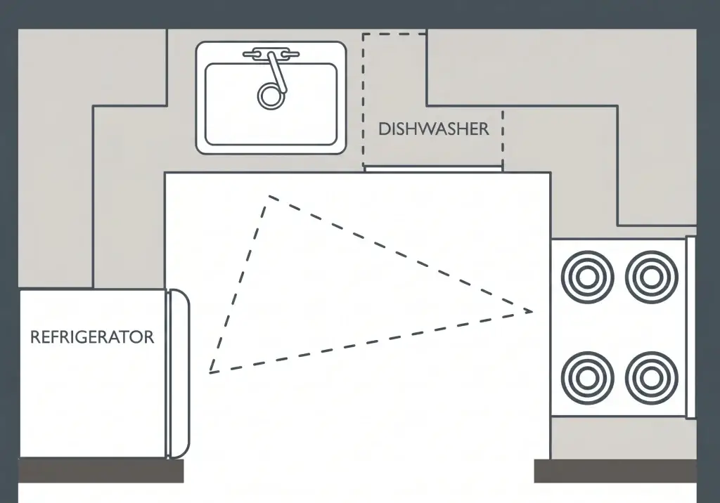
Optimizing the Kitchen Triangle Layout Across Three Perimeter Zones
The architectural advantage of a U-shaped configuration lies in its structural alignment with ergonomic motion physics. By isolating the three primary culinary tasks—cold storage, wet preparation, and thermal cooking—onto three dedicated, adjacent walls, the kitchen triangle layout reaches its highest expression of operational efficiency. According to NKBA guidelines, no single leg of the work triangle should measure less than 4 feet (1.2 meters) nor more than 9 feet (2.7 meters), with the total sum of all three legs falling strictly between 12 feet (3.6 meters) and 26 feet (7.9 meters). Furthermore, no major traffic pathways should intersect any leg of the triangle, a criterion naturally satisfied by the three-sided enclosure of a U-shaped blueprint.
Operational zoning in a high-performance U-shaped kitchen relies on a sequential workflow logic: Raw Food Removal (Zone 3) → Cleaning & Prep (Zone 1) → Thermal Processing (Zone 2) → Plating & Serving. When custom millwork is engineered to support this linear progression, user fatigue is drastically reduced, and countertop clutter is eliminated. Below is the structural and mechanical breakdown of how each wall segment must be specified for optimal trade integration.
Zone 1: Wet Preparation Wall (Primary Window Run) — Anchors the undermount workstation sink and integrated panel-ready dishwasher, maximizing natural lighting and views.
Zone 2: Thermal Cooking Wall (Primary Back Wall) — Houses the high-BTU professional gas or induction range paired with a custom wood or slab-clad vent hood enclosure.
Zone 3: Cold Storage & Tall Pantry Tower (Interior Side Wall) — Consolidates the panel-ready integrated refrigerator tower alongside built-in oven and microwave units to complete the cold-to-prep cycle.
Wall 1: Wet Prep Zone - Kitchen Sink and Dishwasher Cabinet Engineering
The primary sink run typically anchors the central or window-facing wall of the U-shape. When specifying the kitchen sink and dishwasher cabinet assembly, millwork engineering must ensure absolute structural rigidity, vibration damping, and water-impervious material selection. We mandate the use of 3/4-inch (19 mm) 13-ply marine-grade birch plywood for all sink base carcases, coated with a waterproof polyurethane sealer. This eliminates the delamination and warping risks associated with standard particleboard core materials when exposed to plumbing condensation or accidental drain leaks.
To achieve a continuous, luxury aesthetic, the dishwasher must be seamlessly enclosed using custom 3/4-inch end panels and a factory-machined panel-ready appliance door match that aligns perfectly with adjacent drawer reveals. NKBA standards require the dishwasher edge to be positioned within 36 inches (914 mm) of the sink rim for easy transfer of soiled dishware. Furthermore, a minimum 21-inch (533 mm) clear standing space must be maintained between the fully extended dishwasher door and adjacent perpendicular base cabinets, preventing users from becoming trapped in the corner during cleanup operations.
Wall 2: Thermal Cooking Zone - Kitchen Range Hood Cabinetry Integration
The central perpendicular wall serves as the focal cooking station. Integrating a high-BTU professional gas range (such as Wolf, Viking, or Thermador) or an induction cooktop requires custom kitchen range hood cabinetry engineered to withstand extreme thermal stress, grease accumulation, and intense CFM exhaust air velocities. The hood enclosure framing must be anchored directly into structural wall studs using 3-inch heavy-duty cabinet screws, supporting both the internal stainless steel power pack liner and decorative outer cladding—whether rift-sawn white oak veneer or mitered quartz slabs.
From a fire code and engineering safety perspective, the minimum clearance between the cooking surface and the combustible underside of the custom range hood cabinet must strictly measure 30 inches (762 mm) for electric/induction cooktops and 36 inches (914 mm) for commercial-style gas ranges. To protect adjacent wall cabinet end-panels from thermal degradation and moisture warping, metallic heat shields or extended backsplash quartz returns must be specified along the perimeter junctions. Internal ductwork chaser voids must be engineered into the upper cabinet carcase, allowing a 8-inch or 10-inch rigid galvanized duct to pass through without destroying usable interior shelving space.
Wall 3: Cold Storage - Microwave and Refrigerator Cabinet Anchoring
The third perimeter run completes the U-shape, housing the tall appliance ensemble: the panel-ready built-in refrigerator tower and integrated microwave and refrigerator cabinet housing. Placing tall full-height cabinetry at the outer terminus of the U-shape prevents visual blockage, avoids shadow casting across primary preparation counters, and creates a clear aesthetic bookend for the entire kitchen installation.
Architectural integration of panel-ready refrigeration towers (such as Sub-Zero, Miele, or Gaggenau) requires precision cabinet cavity dimensions with tolerances non-exceeding +1/16 inch (+1.5 mm). Integrated power ducts and concealed ventilation channels must be engineered into the toe-kick and top-fillers to ensure heat dissipation for compressor operational efficiency. Adjacent speed ovens or microwave drawers must be installed with dedicated electrical junction boxes built into the rear cabinet void, maintaining flush alignment with adjacent shaker or slab door profiles.
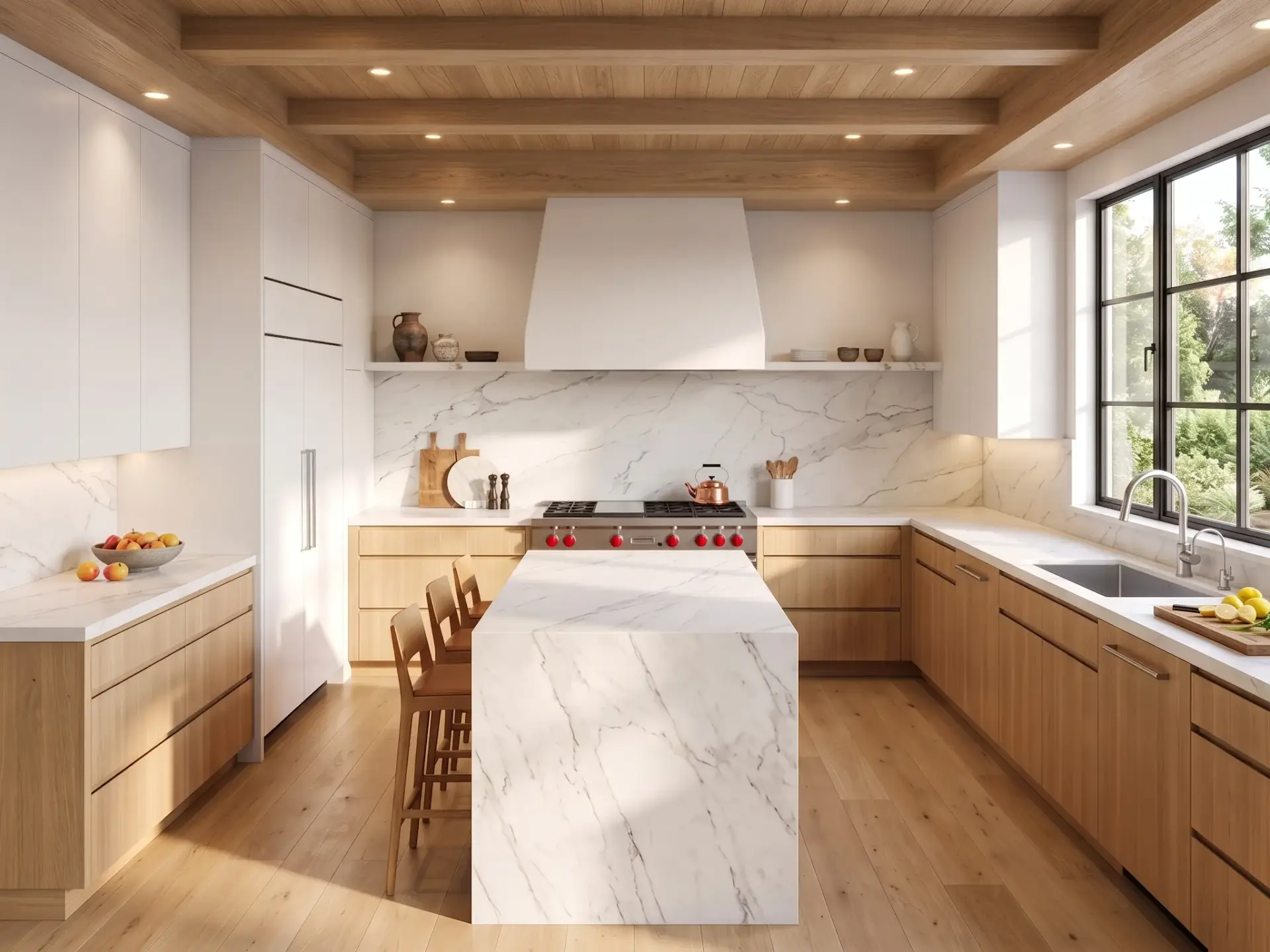
Solving the Two-Corner Challenge: Blind Corner Kitchen Cabinet Ideas & Hardware Engineering
While U-shaped kitchens offer unmatched continuous countertop area and exceptional storage volumetric capacity, they introduce a significant geometric engineering challenge: two 90-degree blind corners. In standard builder-grade or stock cabinet installations, these internal intersection points become dead zones—dark, inaccessible cubic footage where kitchenware is permanently lost. For luxury residential builders, general contractors, and custom millworkers, solving the double-corner issue with advanced blind corner kitchen cabinet ideas and heavy-duty mechanical hardware is a mandatory mark of trade craftsmanship and engineering value.
| Hardware Corner System | Usable Volume % | Max Weight Capacity | Mechanical Complexity | B2B Cost Profile |
| LeMans II Swivel System | 85% – 90% | 55 lbs (25 kg) / tray | Fluid Kinetic Motion | Moderate-High |
| Magic Corner Pull-Out | 80% – 85% | 70 lbs (32 kg) total | Frame Lever Linked | High (Luxury Grade) |
| Diagonal Corner Sink Base | 70% – 75% | N/A (Plumbing Zone) | Stationary Structural | Low-Moderate |
| Dead Corner (Filler Only) | 0% (Wasted Volume) | 0 lbs | Zero Mechanical Parts | Zero Hardware Cost |
📐 Custom U-Shaped Cabinetry Engineering & Full Project Estimation
Planning custom U-shaped casework for an upcoming residential estate or multi-family development? Send us your architectural plans or room dimensions. ALLAND’s engineering desk will optimize your corner storage integration, audit all appliance clearance setbacks, and deliver complete factory-direct shop drawings and an itemized cabinetry quote within 48 hours.
LeMans II Swivel Systems vs. Magic Corner Pull-Outs
To eliminate cubic void spaces, custom base cabinets must incorporate pre-assembled german-engineered corner articulation hardware. The two industry-gold-standard kinetic solutions specified in custom millwork tender documents are the Kesseböhmer LeMans II Swivel System and the Magic Corner Pull-Out.
The LeMans II system utilizes smooth curve kinetic motion, extending both height-adjustable trays entirely outside the cabinet carcase cavity. Each tray boasts a mechanical weight rating of 55 lbs (25 kg) and requires an opening door angle of just 85 degrees, making it immune to collisions with adjacent handle hardware on opposing cabinet runs. Conversely, the Magic Corner system utilizes a frame-mounted lever mechanism that automatically pulls the rear storage baskets into clear view when the front door panel is opened. While offering a higher structural payload (up to 70 lbs total), the Magic Corner requires precise internal cabinet clearance tolerances (+/- 1 mm) and reinforced 3/4-inch cabinet carcase side-walls to prevent long-term hinge sag under maximum loading conditions.
Preventing Door and Drawer Collisions in 90-Degree Corner Junctions
A critical error made by inexperienced cabinet installers in U-shaped configurations is failing to account for door handle and drawer pull projections at the internal 90-degree corner junction. When a base drawer on Wall A is pulled out simultaneously with a cabinet door on Wall B, hardware collision will chip, scratch, or permanently compromise expensive painted lacquer or rift-cut veneer finishes.
To prevent internal corner collisions, custom millwork engineering mandates the installation of a minimum 2-inch (51 mm) corner filler strip or blind-corner return panel between the intersecting cabinet runs. This dimensional buffer ensures that pulls (which typically project 1-1/4 to 1-1/2 inches) clear adjacent cabinet face profiles effortlessly. Furthermore, soft-close hinges with 86-degree or 110-degree integrated angle restrictors should be specified to mechanically lock door swings before impact occurs.
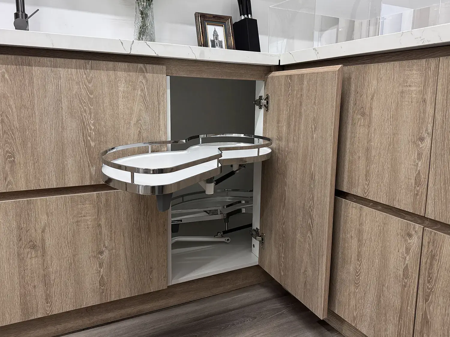
Corner Clearance Buffer Equation:
Required Filler Width = Max Handle Projection + Door Thickness + 0.5″ Safety Tolerance
Example Calculation:
Filler Width = 1.375″ (Pull) + 0.75″ (Door) + 0.5″ (Safety) = 2.625″ (Specify 3-Inch Standard Corner Filler)
U Shaped Kitchen Layout with Island: Spatial Feasibility & Clearance Calculations
In large custom estates, luxury ranch homes, and open-concept residential floor plans, developers frequently seek to combine the boundary isolation of a U-shape with the social entertainment value of a freestanding central island. However, executing a u shaped kitchen layout with island requires exceptional architectural footprint depth and floor plan width. Attempting to force an island into a tight U-shaped envelope restricts clearance aisles, creates severe traffic bottlenecks, prevents dishwasher loading, and renders appliance doors unopenable.
Minimum Required Room Width Equation for U-Shape with Island:
Required Room Width = Left Base Cabinet Depth + Right Base Cabinet Depth + Left Aisle Clearance + Right Aisle Clearance + Island Cabinet Depth
Left Perimeter Base Cabinet Depth: 24 Inches (610 mm)
Right Perimeter Base Cabinet Depth: 24 Inches (610 mm)
Left Work Aisle Clearance (Min): 42 Inches (1067 mm)
Right Work Aisle Clearance (Min): 42 Inches (1067 mm)
Minimum Functional Island Depth: 42 Inches (1067 mm) [Includes 24″ carcase + 18″ seating overhang]
Total Minimum Required Clear Room Width: 16 Feet / 192 Inches (4876 mm)
📐 Custom Island & U-Shaped Casework Feasibility & Factory Package Quote
Wondering if your architectural footprint can comfortably support a custom freestanding island alongside a full U-shaped perimeter run? Send us your architectural floor plans or room sketches. ALLAND’s engineering desk will run a 1:1 CAD spatial feasibility review, optimize seating overhang steel supports, verify all appliance clearances, and provide a comprehensive factory-direct cabinetry package estimate within 48 hours.
Minimum Architectural Footprint Requirements (The 16-Foot Rule)
This dimensional threshold is derived from precise additive engineering parameters: two 24-inch (610 mm) deep perimeter base cabinet runs on opposite walls (totaling 48 inches / 1219 mm), two minimum 42-inch (1067 mm) net clear working aisles on either side of the island (totaling 84 inches / 2134 mm), and a minimum functional island width of 42 inches (1067 mm) to allow for internal storage drawers and breakfast bar knee clearance. If the architectural framing measures less than 192 inches in width, developers must pivot away from a freestanding island and instead specify an extended peninsula run—effectively transitioning the floor plan into a custom G-shaped configuration.
Island Seating Overhang Mechanics and Structural Cantilevers
When specifying breakfast bar seating along the outer profile of an island within a U-shaped layout, millwork engineers must calculate proper knee clearance overhangs and structural cantilever support. For standard 36-inch high countertops, NKBA guidelines mandate a minimum knee clearance depth of 15 inches (381 mm). For 42-inch high raised bar tops, a 12-inch (305 mm) clearance is required.
When specifying heavy stone surfaces—such as 1-1/2 inch (38 mm) mitered Calacatta marble quartz or natural granite—any countertop overhang exceeding 12 inches (305 mm) requires hidden structural steel support to prevent slab cracking, flex-fatigue, or tipping under shear loads. Custom factory fabrication incorporates 3/16-inch (5 mm) thick laser-cut structural steel plates or concealed steel cantilever brackets mounted directly into the island internal plywood sub-framing. This engineered bracing ensures a completely flush, floating aesthetic underneath the countertop without knee-striking vertical corbels or wooden legs.
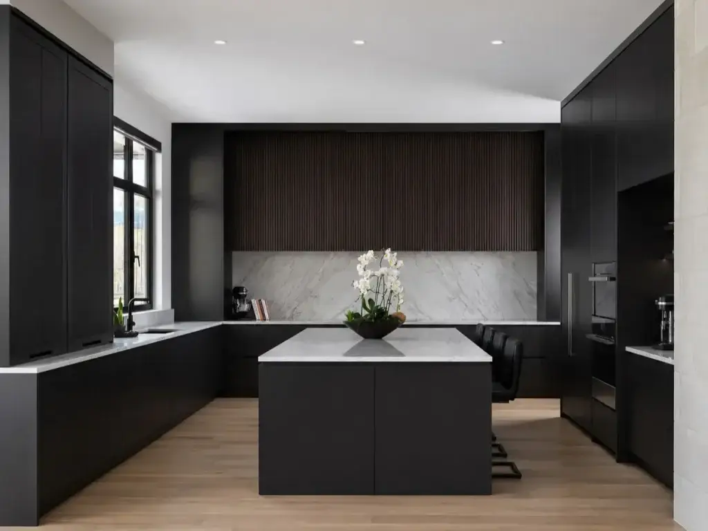
Engineering Kitchen Corner Countertop Ideas: Seam Precision & Structural Support
In a U-shaped kitchen, the horizontal surface plane is just as engineering-intensive as the cabinet sub-structure. Because the countertop run must wrap continuously around two 90-degree internal bends, executing flawless stone transitions requires advanced fabrication techniques. Specifying high-performance kitchen corner countertop ideas involves selecting the correct joint geometry, managing slab veining continuity, and structurally reinforcing heavy engineered quartz or natural marble against building settling stress.
| Seam Engineering Strategy | Structural Integrity | Aesthetic Vein Match | Fabrication Labor Cost | Moisture Resistance |
| 45-Degree Mitered Joint | High (Tension-Bonded Resin) | Exceptional (Continuous Flow) | Premium Custom | 100% Hermetic Seal |
| 90-Degree Straight Butt Joint | Moderate (Shear Vulnerable) | Disrupted Veining Pattern | Standard Field Install | Dependent on Epoxy Maintenance |
| Radius Euro-Slab Joint | High (CNC Machined) | Smooth Angle Transition | High Factory Precision | Fully Sealed |
45-Degree Mitered Seams vs. Straight Butt Joints
Traditional builder installations frequently utilize simple 90-degree straight butt joints at corners, placing the seam line directly adjacent to the sink or cooktop cutouts where mechanical stress and moisture concentrations are highest. In custom commercial-grade millwork, this budget approach is strictly rejected due to high seam visibility, dirt accumulation, and susceptibility to water penetration. Instead, modern architectural specifications demand a 45-degree mitered corner seam or a strategic seam placement offset at least 12 inches away from any appliance or sink cutout.
A 45-degree mitered seam follows the natural bisecting angle of the corner, allowing dramatic marble veining (such as Calacatta Gold or Statuario) to flow continuously across the perpendicular runs without jarring visual interruptions. Stone fabricators utilize 5-axis CNC waterjet cutting and color-matched two-part structural epoxy resin injected under vacuum pressure to lock the seam. Once field-polished flush, the joint achieves an invisible, monolithic appearance with structural tensile strength equal to the raw engineered quartz slab itself.
Sub-Top Reinforcement and Wall Anchor Engineering
Because U-shaped countertops represent massive continuous dead loads—often exceeding 800 to 1,400 lbs of stone—the underlying cabinet carcases must provide flex-free support. Sub-top construction mandates the installation of a full 3/4-inch (19 mm) exterior-grade CDX plywood sub-top under 2 cm stone slabs, or direct perimeter cabinet solid hardwood webbing for 3 cm solid slabs.
At the internal 90-degree corner voids where cabinet carcases meet, wall-mounted steel angle irons (heavy-duty 2×2 inch 1/4-inch thick powder-coated steel ledger bars) must be anchored directly into structural wall studs using 3/8-inch lag bolts. These steel brackets bridge the corner span, preventing long-term countertop sagging, joint separation, or micro-cracking caused by natural structural thermal expansion and frame settling.